I know I separated the Macro updates from this site, but I really wanted to throw these up here, I really like how they’re starting to turn out!


I know I separated the Macro updates from this site, but I really wanted to throw these up here, I really like how they’re starting to turn out!


In the back of my head for a while I’ve had plans to build a jamma box so I can use xbox 360 on a cabinet. Well my Vewlix came a few days ago, and I really wanted to use a 360 in it. The vewlix was wired for Chinese Jamma (which allows buttons 1-6 over one harness) so I figured why not build it for that? I can always use a JNX adapter to make it normal jamma! Anyways, I used the padhacks below that I’ve had sitting in a drawer for a year

Anways, I used a project box and a Jammaboard.com (RIP) jamma edge connector. I feel like it came out pretty nicely!


That’s pretty much it. I just wanted to throw a quick post up!
My Chinese Vewlix (Chewlix?) cabinets came today. This is a relatively short post text-wise, but I have a video on some of the fixes I’ve done so far!


Here’s quick video on some of the fixes I’ve done:

You may or may not know that I LOVE SNK and NeoGeo. There’s something strange about SNK games, some incredible charm they have and I just love it. Maybe it’s the broken English, the weird gameplay, the beautiful visuals, or just everything. But something about them I really get into. Anyways, I’ve wanted a NeoGeo AES for a very long time, I just can’t bring myself to buy one. Then it occurred to me, why should I buy an AES when the MVS games are cheaper and more abundant? I should just build a consolized MVS! Well, I’m in luck since I have an extra MV1FZ board! While it isn’t the MV1C, it is still a one slot board and should do what I want it to do! I’m sure eventually I’ll buy an AES and an Omega though. The parts I’ve chosen are as follows:

Should have posted this a while ago, but I picked up an Atomiswave! It popped up on craigslist and I couldn’t resist it…


Then I picked up a Third Strike board (aka the best Street Fighter ever)


Recently I picked up a New Astro City. It was in pretty rough shape…


Anyways, per usual I broke out the hose and Simple Green (I wonder if I get enough traffic for them to become a sponsor? Probably not). The display was particularly gross. Not as bad as my blast city, but still pretty bad.
So we go from this:


To this:


Now onto the rest of the cab. I didn’t take any photos of the post cleanup, it just took a lot of simple green and water really. This definitely needs to be repainted at some point, but not today. Here was the corpse after the clean.

Not looking too hot next to the blast…
Next up was ripping out the jamma harness and rewiring it. That took probably 4 hours. Wiring is such a pain. On the plus side I did improve a bunch of wiring in the cab from being spliced to using AMP connectors and whatnot.

Shockingly everything worked, including audio.


I then worked on the control panel. Removed the 50 yen sticker that had been placed on it, only to have a 100 yen sticker be underneath that. These 100 yen stickers are so much nicer! In the process of washing the CP the center bolt hole broke off so I had to use some abs cement to weld it back into place, see the hi-tech electrical tape stabilizing it?

With that in place I had to get a new cp, thankfully Jasen (of Jasenscustoms.com) makes some awesome repros so I picked one up from him and applied a new overlay to it 😀


Then it was just a matter of buttoning the baby up! Right now I’m running Darksoft’s CPS2 multiboard in it, I might throw something else in there sometime, we’ll see!

Yay!

So I came across a Sony PVM on craigslist a week ago and couldn’t resist getting it. Since then I’ve fallen down a retro hole. I have a bunch of scart cables on the way, so I’m pretty excited to see how everything looks on it. Scart is actually kind of complicated, who would have thought? My head just about exploded trying to differentiate between Composite Sync and Composite Video + Sync. Still not sure I totally get it. Anyways, it resulted in my picking up a new snes, model 1 genesis (original with “High Definition”), saturn, and hooking up my n64 and ps2.
I ended up doing a stereo mod to the Genny after cleaning it out, pretty pleased with how clean it turned out!


Now I just have to clean up these bad boys

I noticed the snes has the center pin for the power jack broken off. I ordered a replacement, but I’m considering doing something weird like internalizing the PSU and putting a figure 8 connector on it or something. That could be neat.
Anyways, this TV is fantastic, I need to find a better place for it.


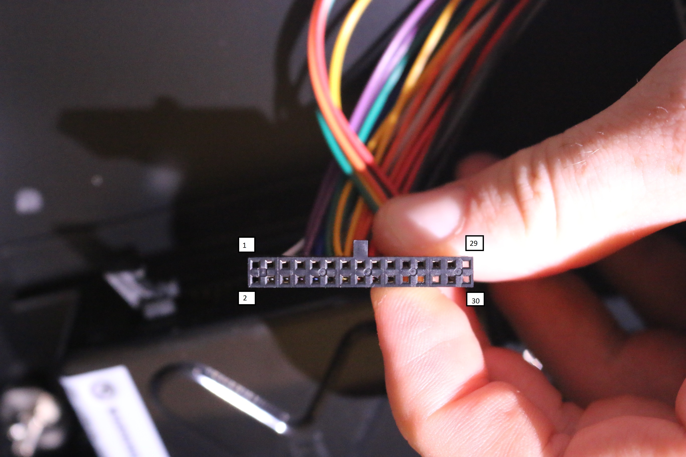
This is mostly for reference as I’m starting to look into modding my Hori VLX! But if anyone needs it:
Pin Spacing: 2.54mm or .100″
Connector Dimensions: 38.15mm x 5.09mm
Pinout:

For clarification, the pin layout is as follows!
PS: I picked up an astro city today. So I’m going to start posting about that soon 😀


Items you will need:
First, turn the DS over, remove the battery cover and then remove the screws marked in red.


Once these screws have been removed you can pry the DS case open. It is a bit of a pain, but remove the bottom first, leave it so the bottom screen is laying face down or else you risk damaging the ribbon cable.
Start at right side and slowly pry around to the left side until you can lift it up. Lift it up slowly, the springs in the L and R buttons may pop out.
Once open, remove the screws and disconnect the cables marked in red. Then remove the Wifi/Bios module (marked in blue).
Note: It may be difficult to remove the wifi antenna (black). You can try to feed it through the DS slot, but it will probably get caught on something. Since we’re not going to need it I usually just cut it off.

There is some double sided tape holding the right side of the bios module down, so it will be slightly tough to remove
Next, you need to disconnect the digitizer ribbon cable, the connector is VERY fragile. Lift it up from the bottom with a tooth pick or something similar

Now, push the touch screen from the outside and lift the motherboard out. You can flip the motherboard up from the bottom and rest it on the table (see below). Then disconnect the ribbon cables marked. Then remove the screws marked.


Now you can remove the top half of the shell from the board and remove the touch screen. Feed the ribbon cable through the slit like you see below. If you have no plans of using the top screen then you could also just cut the cable.

You now need to solder the 330 OHM SMT resistor (or resistor of your choice) to the points marked below. LEDC2 and LEDA2. Orientation does not matter
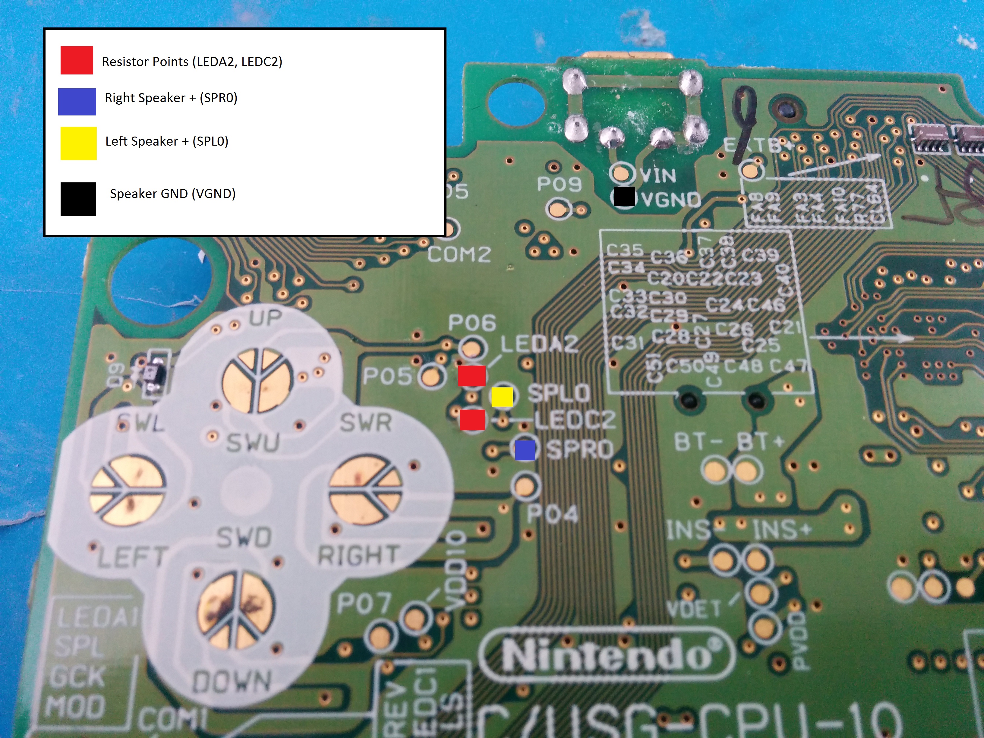
I have found that the easiest way to install these resistors is to first pool solder on the points (see below), then use a pair of tweezers to hold it to the points while heating the pool of solder. The resistor will lower to the point then you can solder the next point.


You can test it if you’d like, but it should work now.
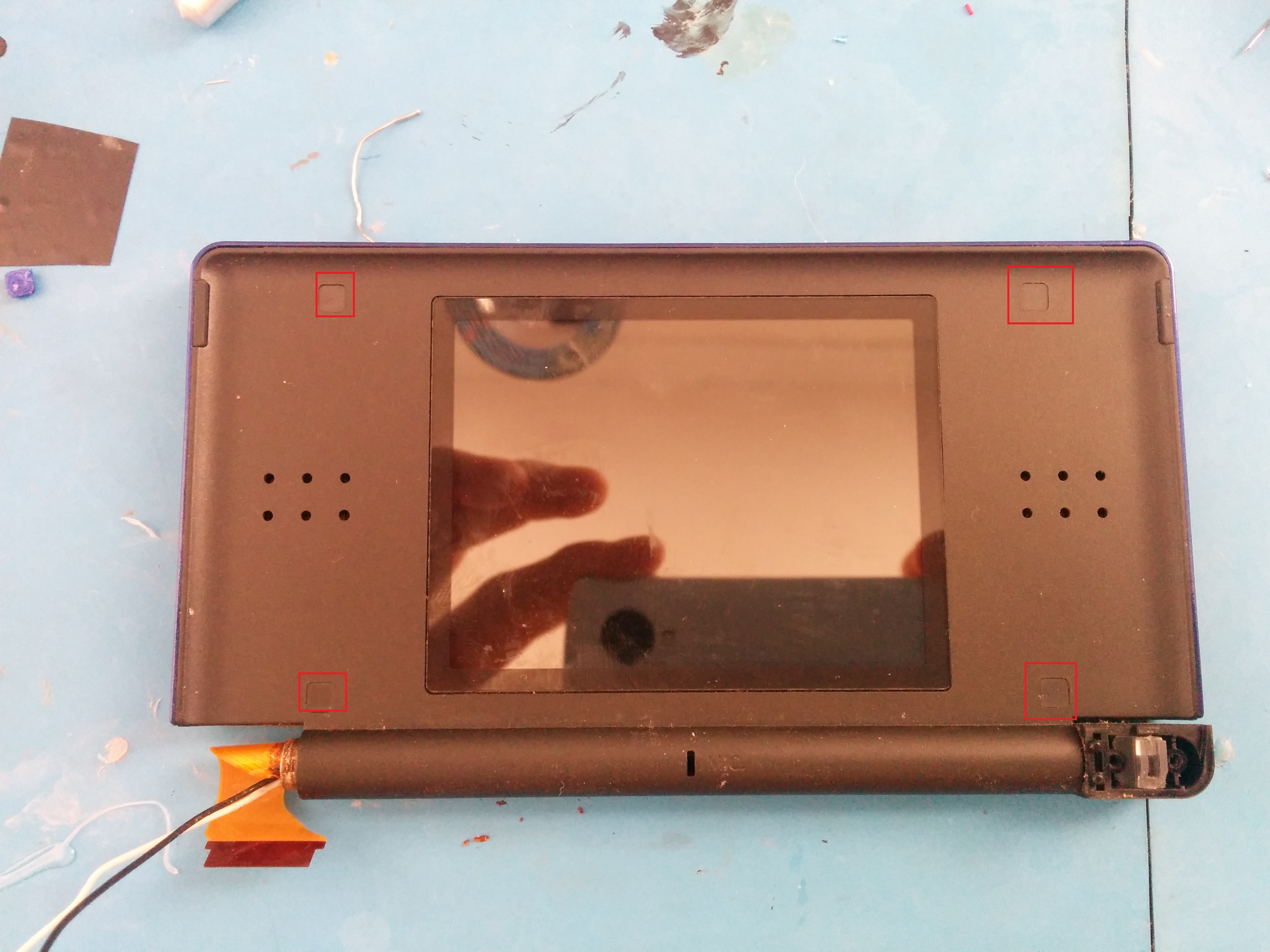
Now it’s time to get the speakers. Get the top screen and remove the covers marked in red. Then remove the screws under them.
Now you need to flip it over, and pry the back off. Just do the same as you did on the case and slowly work around. I usually start at the hinge since that’s easy to separate. Once it’s open you should see something like this.

You’ll need to remove the ribbon cable holding the screen in. You can either cut it, or roll it up and slip it through the metal ring.

Once it’s out, push the screen out from the front of the case (just push against the plastic), and it will come out, speakers and all. Then desolder one or both sets of speakers marked below.
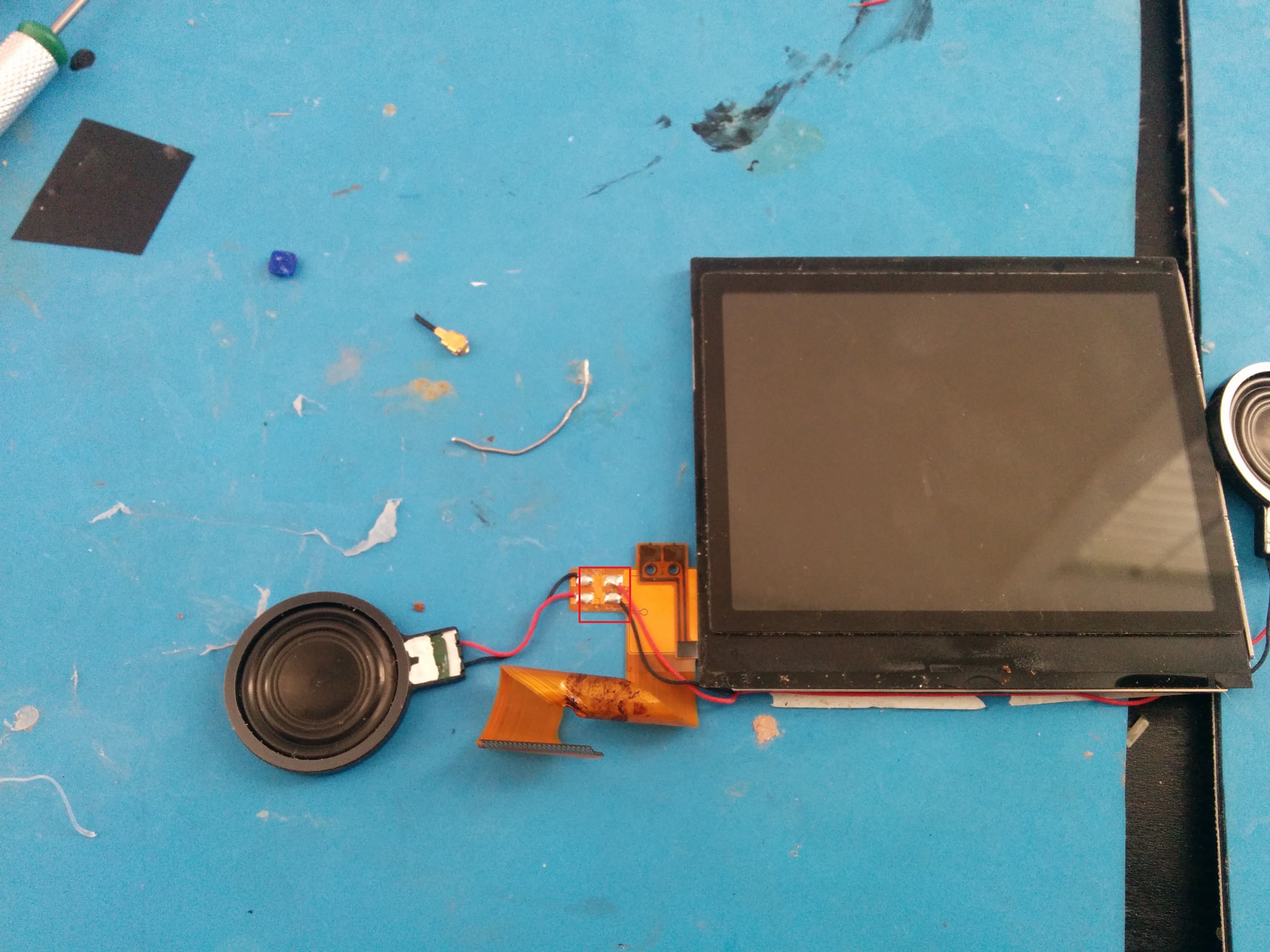
Next cut two strands of kynar wire (maybe four inches in length, you can always trim it later) and solder it to the connectors on the speaker.
Return to the motherboard and flip it over. Run the speaker wire under the DS slot like so. Just let the speaker magnetize to the motherboard for now. You will need to remove it to screw the motherboard into your case after you finish your mod. Once it’s screwed in you can glue the speaker down.
Next, flip the motherboard over and solder the speakers to the points marked below. This tutorial will only include the right speaker. But if you want to use the left as well, solder it to the point referenced.


Now you can hook the battery up, plug the screen in and test it!
I’m cross posting this tutorial here for anyone who isn’t following gameboymacro.com!
Items you will need:
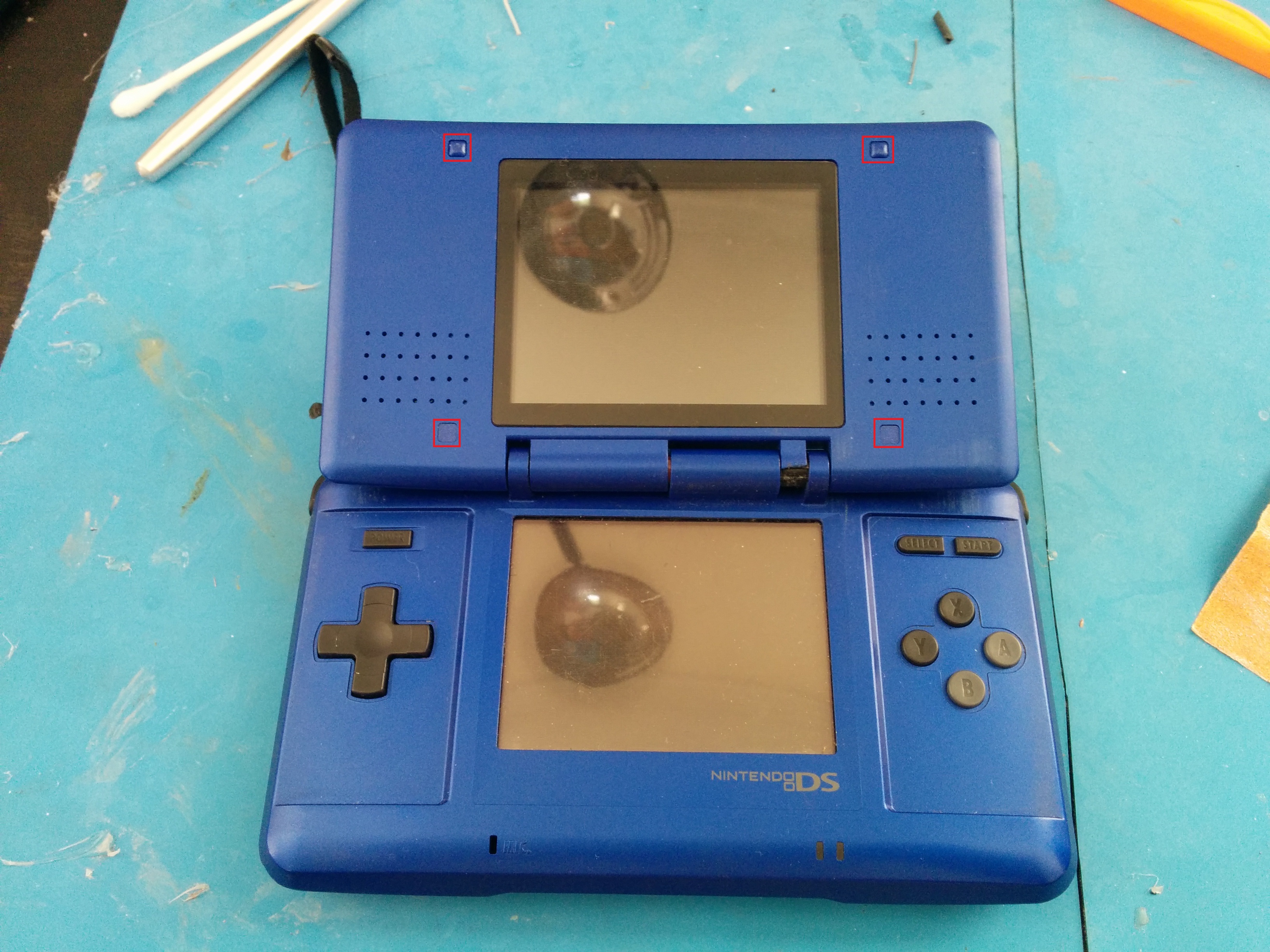
This is a fairly simple step. Using the tri-wing screwdriver, removed the screws from the points marked in red below.

After the screws are removed simply lift the rear of the shell to reveal the innards of the DS. Once opened, remove the screws marked in red.
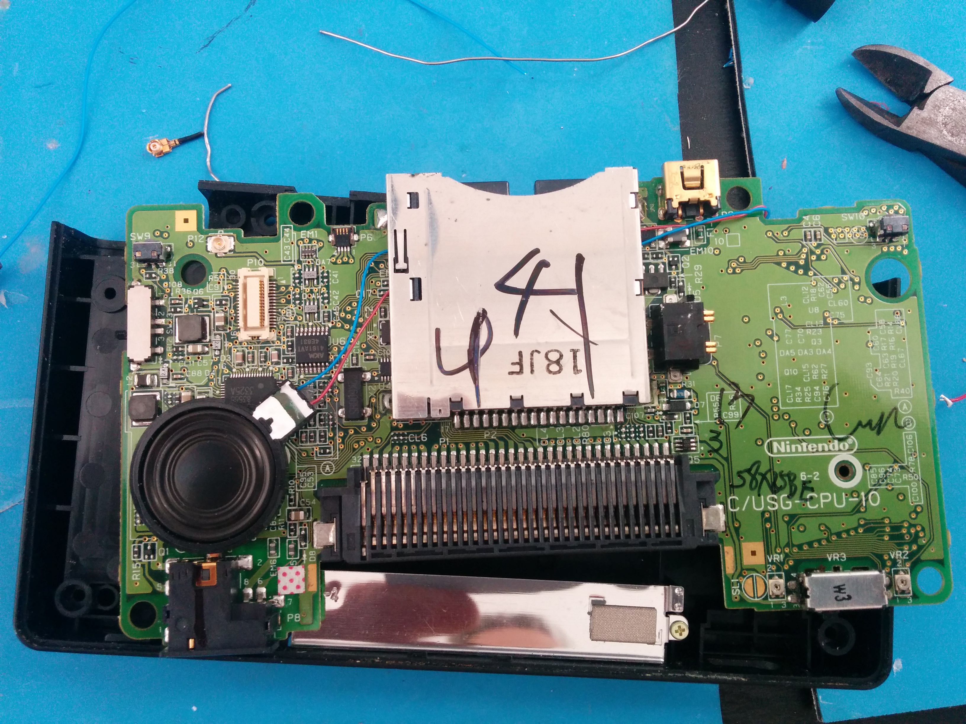
Once removed disconnect the Wifi antenna cable, and the ribbon cables marked in red. Do not remove the motherboard yet, first lift up the bottom screen large ribbon cable to reveal two smaller cables below it. Remove those as well. These two ribbon cables are removed by pulling the brown locking mechanism forward. Do it slowly and softly, it is fragile (if you break it you can fix it with somewhat of a workaround). Once these are all removed you can remove the shoulder buttons and lift the motherboard from the shell.


With the motherboard out you are ready to solder the resistor! Get your 330 OHM resistor. If you are using an SMT resistor I would recommend getting some tweezers for this, as they are freaking tiny.
Soldering these is difficult (mine are rarely perfectly straight. The easiest way I’ve found is to pool solder on your two points, then lay one side of the resistor on the pools. When you heat the first side with your soldering iron it will suck the resistor in. Repeat with the other side and it will do the same, then the resistor will be level and soldered.
The points you are soldering to are marked in red below, they are LEDC2 and LEDA2. The orientation of the resistor doesn’t matter.


That is all you need to do to run the DS headless. You can plug the bottom screen in and test it if you’d like.
In this tutorial I am only installing one speaker (the right one). If you would like to use both left and right then just solder the the left speaker point as well.
First, remove the covers from the areas marked below, then remove the screws.

After the screws are removed pry the back of the screen off to reveal the inside.

Remove the screws holding the two small boards in. Now you have two options here. If you have 30 gauge kynar wire you can just use that, if not, remove the longer black and red wires connecting these two boards and solder them to the speaker as seen below.

You can then either wrap this connection in electrical tape, or just put a dab of hot glue on it to insulate it.
Now you can remove the top screen housing entirely. Remove the screw seen below

Once removed, you just have to wiggle the top housing off of the hinge and sort of finesse the ribbon cable for the top screen out. It really doesn’t matter if you rip the ribbon cable unless you plan on using the screen in something else.
Now you’re ready to install the speakers, reference the image below again for the proper points. This tutorial only installs the right speaker.
Solder your speakers to points:


You can now test it if you’d like. Plug the bottom screen back in. It should work like this:
Now, flip the motherboard over to reveal the back. This part is super simple. If you have a hot glue gun, plug it in and wait for it to heat up. Then glue the speaker down in the area marked below. Double-sided tape will also work if you don’t have a glue gun.


That’s all. It should work now! Soon I will have a tutorial up for cutting and filling the case. But that’s all you need to do for the bare minimum. If you don’t need a speaker you could just put it back together and play like it is, just with headphones.