A few months ago I received a free Sega Nomad from a friend. It has more or less been sitting in a closet with all of my other Sega games, mostly unused. The issue with the Nomad was that the battery compartment was missing, so realistically this thing was unusable. I finally decided to tear it apart and integrate some rechargeable batteries for it. This was mostly done with parts I had lying around. So what I used for this was:
Two knock-off Chinese DS Lite batteries (I have a ton of these from macro work)
A spare 7.4v charging circuit
Spare 7.4v smart battery charger.
This is less of a tutorial post and more of an image dump. As of right now, the battery portion of the mod is complete, but the LCD portion is not. The LCD had some syncing issues with the Nomad, so I ordered another one. I will post a much more in-depth and tutorialized post once that is all finished. But for now, here are all of the images of the mini project.
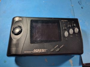
Plain ol’ Nomad
This is the nomad’s butt
Daughterboard. Well at least that’s what I’d call it.
Back of the nomad
The batteries on the right are what I wanted to used. But they would not have fit without a lot of case reworking
A bit fuzzy on how i ended up wiring this. I believe ultimately I went with cutting the power traces at the DC port. Wiring the batteries to the DC port. Then also wiring the + terminal of the battery to + terminal on the original battery connector. That way the battery LED was still functional.
A few weeks ago I had the urge to get a backwards compatible PS3. I’ve had a few in the past, but they seem to eventually die of YLOD. I decided to pick a YLOD console up off of ebay for $30 and fix it. I did the standard reflow as a repair, as well as replaced the thermal paste on the IHS for the GPU and Cell processor in some crazy dream that it will keep going if I do that.
In addition to that, I also decided to make an adjustable fan mod. I did this fairly simply, and you can see the photos below on how to do it yourself if you’d like.
Initially I was just going to mount a POT to the front and use it for fan adjustment, I eventually decided it might be beneficial to also put a switch in so I can switch between the fan being controlled by the PS3 and the fan just being controlled by the POT. Keep in mind, this POT isn’t really the perfect rating (250k I believe), but it works fairly well and I had it on hand. As well as a random DPDT switch. The mounts aren’t perfect, but I’ll clean them up in a bit, this is just a quick hour long project.
Connect the grey wire from the fan to the dpdt switch. The wire going to the motherboard will be sent to another point on the switch, and the POT will go to the final remaining pole.
Just a little DPDT switch to control it
Quick shot of the mount on the front. Seems to work fairly well.
So I came across a Sony PVM on craigslist a week ago and couldn’t resist getting it. Since then I’ve fallen down a retro hole. I have a bunch of scart cables on the way, so I’m pretty excited to see how everything looks on it. Scart is actually kind of complicated, who would have thought? My head just about exploded trying to differentiate between Composite Sync and Composite Video + Sync. Still not sure I totally get it. Anyways, it resulted in my picking up a new snes, model 1 genesis (original with “High Definition”), saturn, and hooking up my n64 and ps2.
I ended up doing a stereo mod to the Genny after cleaning it out, pretty pleased with how clean it turned out!
Now I just have to clean up these bad boys
I noticed the snes has the center pin for the power jack broken off. I ordered a replacement, but I’m considering doing something weird like internalizing the PSU and putting a figure 8 connector on it or something. That could be neat.
Anyways, this TV is fantastic, I need to find a better place for it.
I recently got a hold of two Wonderswans and decided I wanted to front light at least one of them. After some research I found this screen. The screen seems to be the proper dimension for front lighting the wonderswan, and it was on sale for $3! So I grabbed four of them (in retrospect I should have gotten like 20 of them).
They came yesterday and I tore the thing apart and started off on frontlighting it. This will serve as somewhat of a guide for doing this.
First we start with the donor screen.
The donor screen.
Wedge a screw driver in the opening to pry the metal away from the clips
Pull away and you’ll reveal the front light and diffuser right there.
Small update to the macro. I dremeled down the case, and did the first application of bondo. Pretty rough so far. But I hope it looks good. Right now I think I’m going to paint it grey.
Hinge areas removed
Screw mounts for the stylus removed, and a few of the walls are removed.
Bondo’d up yo.
The SMT resistors came as well, so I just replaced that resistor with a tiny one. So far so good!
Yay!
Update 4/23/2015
Sanded and ready to paint. I should finish this very soon. I’m not sure if I should drill the speaker holes before or after painting. Guess I’ll figure that one out.
Pretty cool how well bondo can clean up.
I then found the most high tech way to drill evenly spaced speaker holes
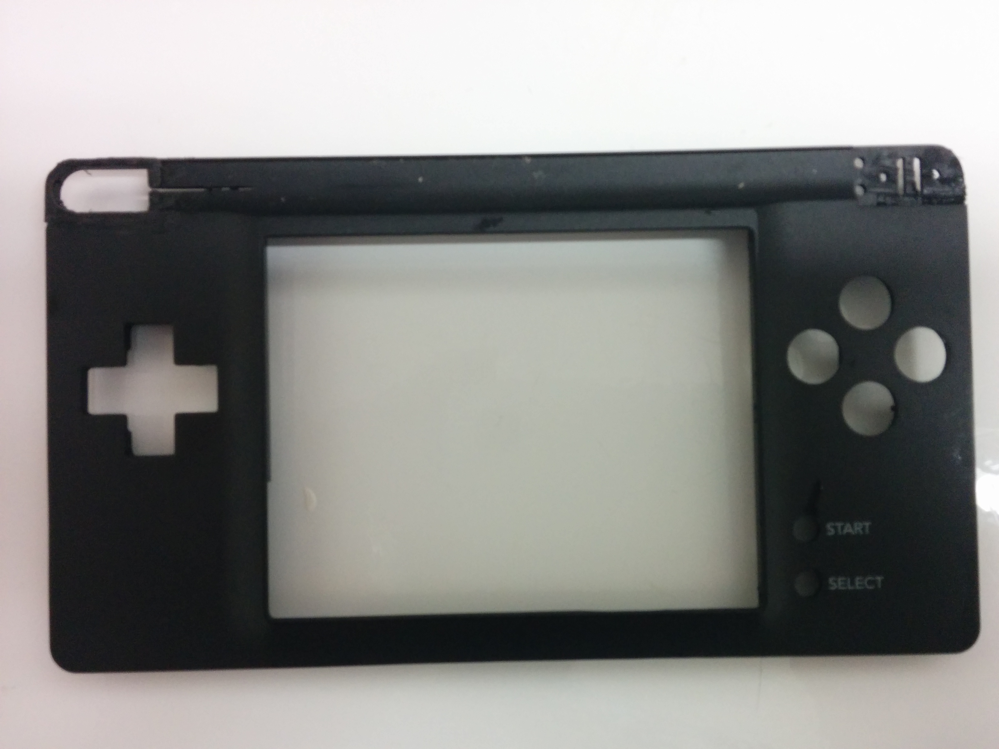
I’ve been looking for a new, more simple project to take on and noticed a lot of these DS Lites without the top screen. The idea is basically the opposite of a Game Boy Micro, a big GBA. In addition to just being a better design ergonomically, you’d be able to throw an R4 in it and emulate GB and GBC games on the bottom screen. It seemed like a cool idea so I ordered a broken DS Lite (non working top screen) off of ebay for $10.
Super dirty DS Lite
Anyways, after tearing it open, I started working on it, and noticed it will not boot without the top screen. I found some stuff online where people had identified two solder pads on the main board, LEDA2 and LEDC2 as being the power for the top screen backlight, and those leads powering something is really all it needs to “trick” the DS into thinking the top screen is there. Many people stated that a single LED would do it, but that simply didn’t work for me. I ended up hooking the leads up to a breadboard and testing various combinations.
The moment I got it working.
I managed to get it to boot with multiple LEDs, but really, another LED just seems like the dumbest way to do this. Why would I want a second power led on this thing? I decided testing resistors, and eventually got it to work with a 330 OHM resistor. Lower OHM wouldn’t boot, and when I tried a 1k resistor the screen was just incredibly dark, 330 OHM seemed to be the sweet spot where it was normal brightness and I could run through all of the different levels as well.
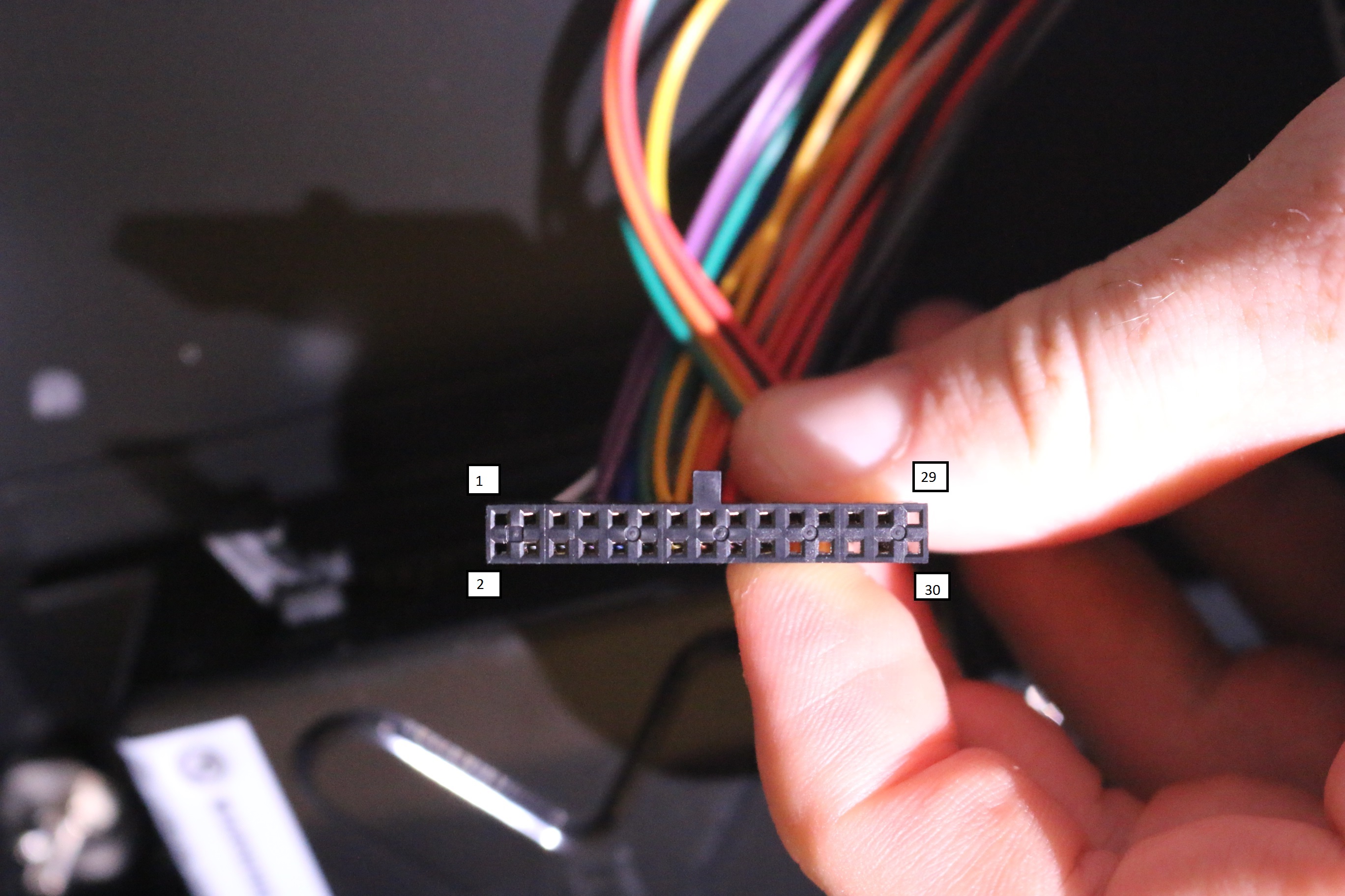
Speaker points for future reference
I then broke out my multimeter and tried to find the speaker connections, it was actually really (really) easy. Literally the first points I probed were the connections. They’re just 45, 44, 43, and 42 of the top screen ribbon cable.
When taking apart the DS I was a bit too hasty, and accidentally destroyed the ribbon connector for the touchscreen, my bad. So I had to go about fixing that. It wasn’t too big of an issue, just using 30gauge wire and protecting it with some hot glue. After that, the touchscreen works as normal.
My bad.
I had to slowly sand down the plastic to get to the copper.
One thing I neglected to do was to take a video of it working, so you’ll just have to take my word for it. So after all of that I decided to hardwire the resistor and test the ol thing.
The shell fits fine, and boots as it should, so it seems to be good placement. This is likely temporary, I’m going to order some surface mount resistors so I can make this much smaller.
That’s pretty much it for now. This is an overall simple mod. I’ll probably finish it before next week. All I have to do now is relocate the speakers (most likely to the rear of the unit, and cut/fill the unused portions of the case.
Minor Update (4/21/2015):
I decided I’d rather get the speaker sorted out last night. If I remove the stylus completely then there is a spot on the back which is pretty much perfect for the speaker. The DS will be mono, but that’s not a big deal, I can always use headphones. I think I can put the wifi antenna on top of it as well, and just drill a couple of holes through the antenna for the speaker to go through.
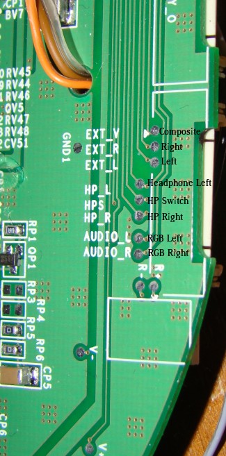
Since all of mod retro’s old diagrams are being purge from photobucket I figure I should rehost them up here for my own reference and anyone else who may need them.
The diagrams on modretro seem to be gone, so I figure I should post this up here for my own reference. The DPDT wiring to have a power jack to charge and a power jack to play is as follows
This results in: Center off, top to play off of external power, bottom to play off of battery.
Just a quick update. I performed the PSOne LED Mod to my screen to save battery life, and because the the backlight burned out. It went fairly smoothly, though I blew out a few leds. Most things I’ve read recommend a 20ohm resistor, which seemed insanely low. I ended up going with 100ohm, which gives me a very visible level of brightness. I used four LEDs instead of the typical two.
I also removed the backlight fuse, and cleaned up the electrical tape that was all over the other wires on the portable.