Up to date tutorials and information on Macros can be found on http://gameboymacro.com/


Items you will need:

Step 1 – Opening the DS

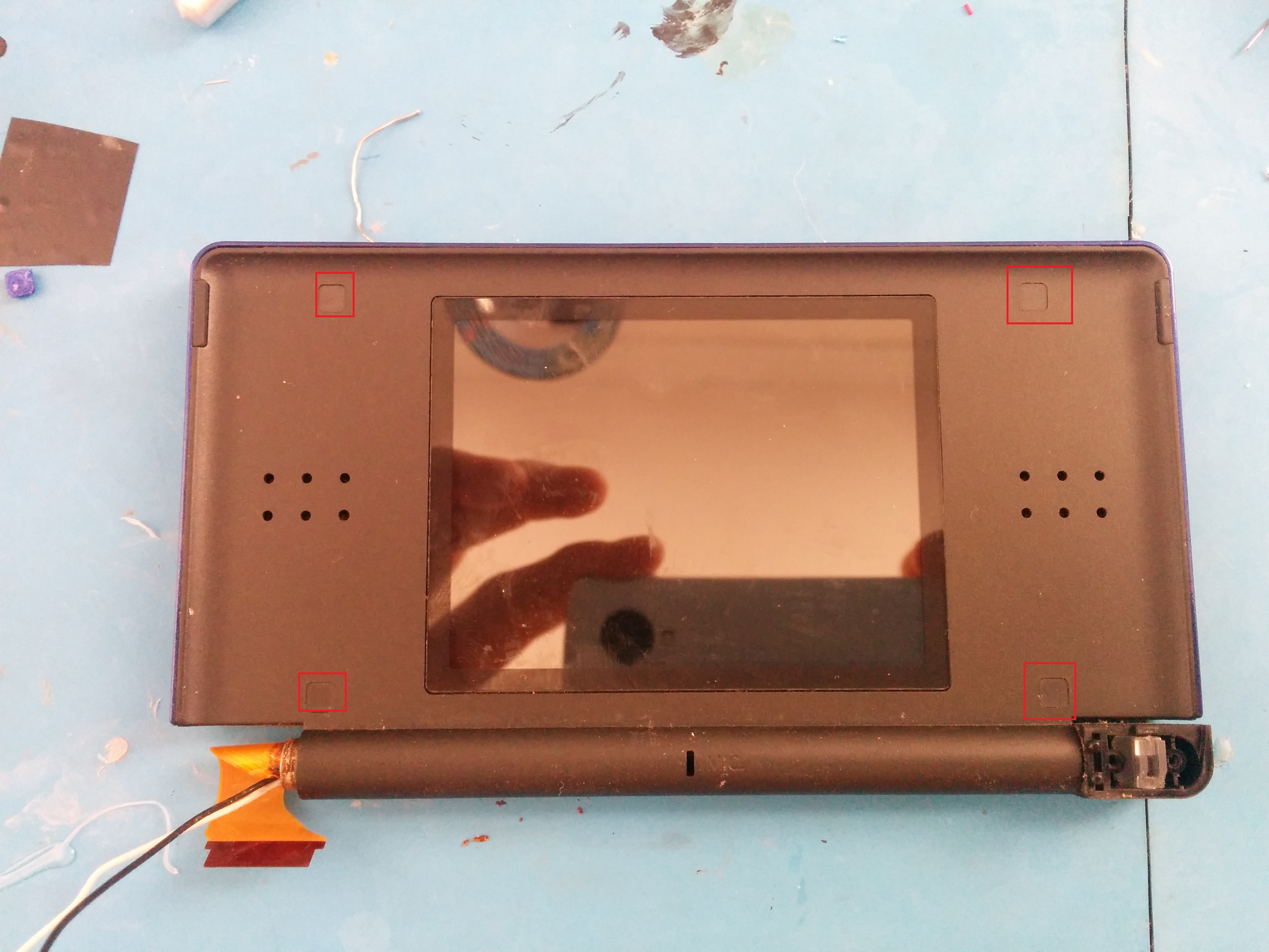
First, turn the DS over, remove the battery cover and then remove the screws marked in red.

Once these screws have been removed you can pry the DS case open. It is a bit of a pain, but remove the bottom first, leave it so the bottom screen is laying face down or else you risk damaging the ribbon cable.

Start at right side and slowly pry around to the left side until you can lift it up. Lift it up slowly, the springs in the L and R buttons may pop out.

Once open, remove the screws and disconnect the cables marked in red. Then remove the Wifi/Bios module (marked in blue).

Note: It may be difficult to remove the wifi antenna (black). You can try to feed it through the DS slot, but it will probably get caught on something. Since we’re not going to need it I usually just cut it off.

There is some double sided tape holding the right side of the bios module down, so it will be slightly tough to remove

There is some double sided tape holding the right side of the bios module down, so it will be slightly tough to remove

Next, you need to disconnect the digitizer ribbon cable, the connector is VERY fragile. Lift it up from the bottom with a tooth pick or something similar

IMG_20150514_160340


Now, push the touch screen from the outside and lift the motherboard out. You can flip the motherboard up from the bottom and rest it on the table (see below). Then disconnect the ribbon cables marked. Then remove the screws marked.

Step 2 – Soldering the resistor

Now you can remove the top half of the shell from the board and remove the touch screen. Feed the ribbon cable through the slit like you see below. If you have no plans of using the top screen then you could also just cut the cable.

IMG_20150514_171347


You now need to solder the 330 OHM SMT resistor (or resistor of your choice) to the points marked below. LEDC2 and LEDA2. Orientation does not matter

IMG_20150514_160944


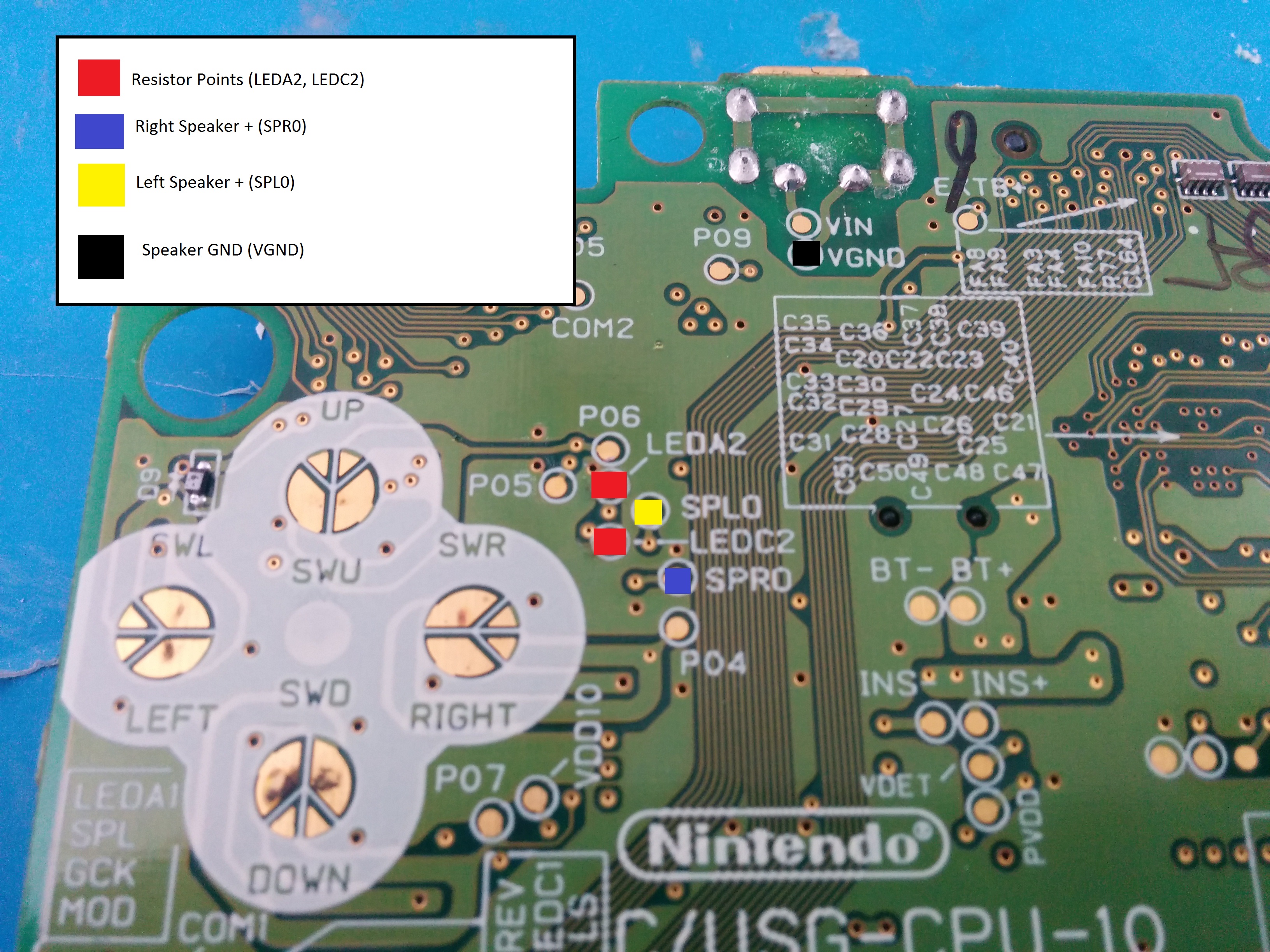
I have found that the easiest way to install these resistors is to first pool solder on the points (see below), then use a pair of tweezers to hold it to the points while heating the pool of solder. The resistor will lower to the point then you can solder the next point.

You can test it if you’d like, but it should work now.

Step 3 – Getting the speakers

Now it’s time to get the speakers. Get the top screen and remove the covers marked in red. Then remove the screws under them.


IMG_20150514_171407

Now you need to flip it over, and pry the back off. Just do the same as you did on the case and slowly work around. I usually start at the hinge since that’s easy to separate. Once it’s open you should see something like this.

IMG_20150514_171719


You’ll need to remove the ribbon cable holding the screen in. You can either cut it, or roll it up and slip it through the metal ring.


IMG_20150514_171818

Once it’s out, push the screen out from the front of the case (just push against the plastic), and it will come out, speakers and all. Then desolder one or both sets of speakers marked below.

IMG_20150514_171831

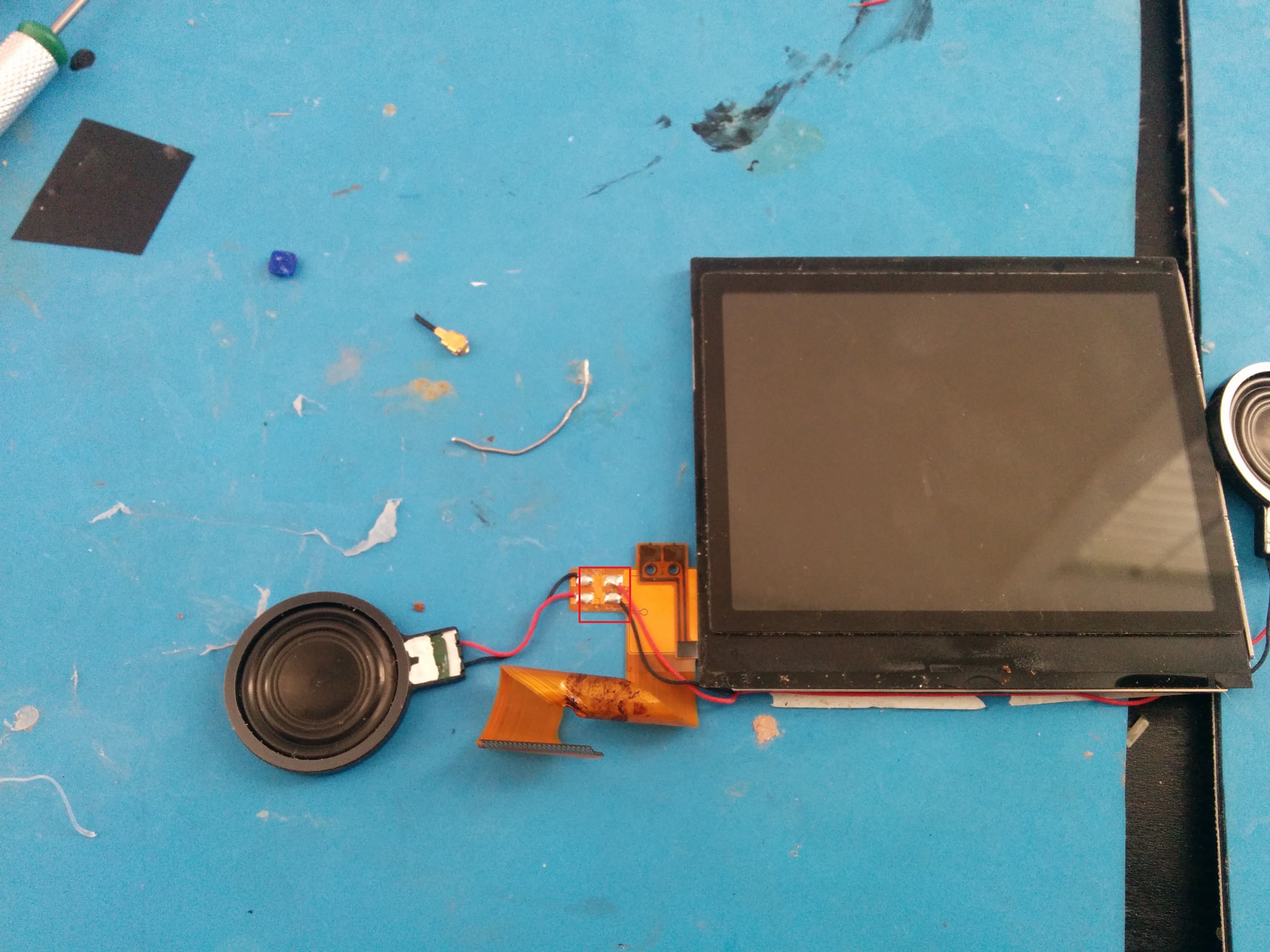
Next cut two strands of kynar wire (maybe four inches in length, you can always trim it later) and solder it to the connectors on the speaker.

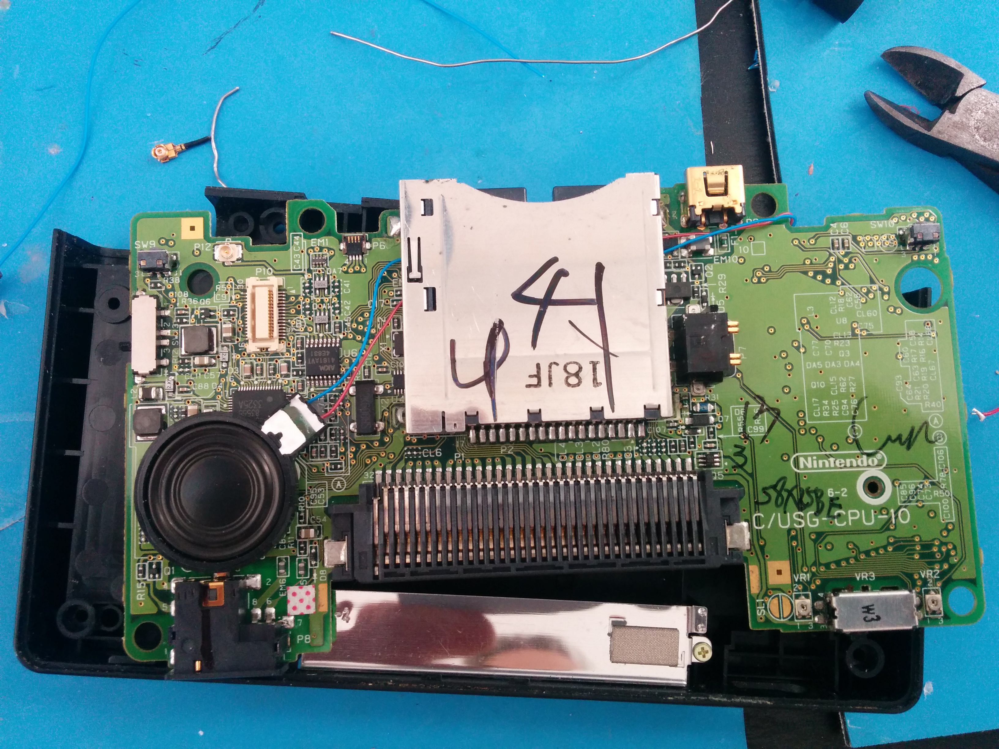
Return to the motherboard and flip it over. Run the speaker wire under the DS slot like so. Just let the speaker magnetize to the motherboard for now. You will need to remove it to screw the motherboard into your case after you finish your mod. Once it’s screwed in you can glue the speaker down.


IMG_20150514_173644

Next, flip the motherboard over and solder the speakers to the points marked below. This tutorial will only include the right speaker. But if you want to use the left as well, solder it to the point referenced.

  • Right = SPR0
  • Left = SPL0
  • Ground = VGND

Now you can hook the battery up, plug the screen in and test it!


I’ve been looking for a new, more simple project to take on and noticed a lot of these DS Lites without the top screen. The idea is basically the opposite of a Game Boy Micro, a big GBA. In addition to just being a better design ergonomically, you’d be able to throw an R4 in it and emulate GB and GBC games on the bottom screen. It seemed like a cool idea so I ordered a broken DS Lite (non working top screen) off of ebay for $10.

IMG_20150413_200424

Super dirty DS Lite

IMG_20150413_200430


Anyways, after tearing it open, I started working on it, and noticed it will not boot without the top screen. I found some stuff online where people had identified two solder pads on the main board, LEDA2 and LEDC2 as being the power for the top screen backlight, and those leads powering something is really all it needs to “trick” the DS into thinking the top screen is there. Many people stated that a single LED would do it, but that simply didn’t work for me. I ended up hooking the leads up to a breadboard and testing various combinations.

IMG_20150420_203541

The moment I got it working.

I managed to get it to boot with multiple LEDs, but really, another LED just seems like the dumbest way to do this. Why would I want a second power led on this thing? I decided testing resistors, and eventually got it to work with a 330 OHM resistor. Lower OHM wouldn’t boot, and when I tried a 1k resistor the screen was just incredibly dark, 330 OHM seemed to be the sweet spot where it was normal brightness and I could run through all of the different levels as well.


IMG_20150420_201959

Speaker points for future reference


I then broke out my multimeter and tried to find the speaker connections, it was actually really (really) easy. Literally the first points I probed were the connections. They’re just 45, 44, 43, and 42 of the top screen ribbon cable.


When taking apart the DS I was a bit too hasty, and accidentally destroyed the ribbon connector for the touchscreen, my bad. So I had to go about fixing that. It wasn’t too big of an issue, just using 30gauge wire and protecting it with some hot glue. After that, the touchscreen works as normal.


IMG_20150420_214741

One thing I neglected to do was to take a video of it working, so you’ll just have to take my word for it. So after all of that I decided to hardwire the resistor and test the ol thing.

The shell fits fine, and boots as it should, so it seems to be good placement. This is likely temporary, I’m going to order some surface mount resistors so I can make this much smaller.


That’s pretty much it for now. This is an overall simple mod. I’ll probably finish it before next week. All I have to do now is relocate the speakers (most likely to the rear of the unit, and cut/fill the unused portions of the case.

Minor Update (4/21/2015):

I decided I’d rather get the speaker sorted out last night. If I remove the stylus completely then there is a spot on the back which is pretty much perfect for the speaker. The DS will be mono, but that’s not a big deal, I can always use headphones. I think I can put the wifi antenna on top of it as well, and just drill a couple of holes through the antenna for the speaker to go through.


The diagrams on modretro seem to be gone, so I figure I should post this up here for my own reference. The DPDT wiring to have a power jack to charge and a power jack to play is as follows

DPDTWiring


This results in: Center off, top to play off of external power, bottom to play off of battery.


This will allow you to view battery levels


This could be used if you want only one charge port. But would require a powerful smart charger.

Just a quick update. I performed the PSOne LED Mod to my screen to save battery life, and because the the backlight burned out. It went fairly smoothly, though I blew out a few leds. Most things I’ve read recommend a 20ohm resistor, which seemed insanely low. I ended up going with 100ohm, which gives me a very visible level of brightness. I used four LEDs instead of the typical two.

I also removed the backlight fuse, and cleaned up the electrical tape that was all over the other wires on the portable.

I’ve realized, after getting this thing booting off of batteries, there really isn’t much I can do with it until I get the case situation sorted out. I need to get some stuff mounted before I can start putting in the controls and finally using the DB15 connector (what could that be for?!). I came across this toy, Datamax KidzDelight. It’s large without being too large and cheap. Unfortunately they’re very rare to find, and common for this project. But fortunately for me there was one on ebay the moment I was looking so I bought it immediately. $12.

Enter the Datamax Kidz Delight….

IMG_20140927_190248
The plan is to do the following:
IMG_20140927_190254

So, let us begin. I first chopped down the ps one screen, then cut a large enough slot for the screen in the DataMax

IMG_20140927_205051IMG_20140927_192010
Well, it looks good to me. Lets start gluing this thing in. Yes, this thing will look like a huge mess, but hey, I’m gonna sand it and fill it, and sand it some more….Then cut it up some more, but the case as it stands looks pretty damn good
 IMG_20140930_132940 (2)
As an added bonus, I did manage to get the analog stick working on the superpad. I’m thinking about using a ps2 analog and using left click for pause. Not entirely sure yet. I’ll go into detail on that as this whole project proceeds. As of now I’ve caught up, so I’ll post more when I have more.


So now that I’ve found the n64 again, where do I start off? It’s been four years, I remember fuck all about this thing, back to ModRetro I go…

After re-reading all of these schematics and fun stuff, I decided I knew what I needed to do to finish this thing, and ordered everything I need!

  • PS2 Analog Stick
  • Gamecube Controller
  • Another N64 Controller. This controller has a far better shell suitable for making a case out of. Though the board likely wouldn’t work.
  • More TI Power Regulators
  • Prototyping Boards for mounting the buttons
  • Hobby Box
  • DB15 Connectors (We’ll touch on that later)
  • Push-buttons
  • BM LP-E6 batteries
Anyways. I finally got around to wiring up the power regulator, which ended up looking a bit like this:
IMG_20141005_023402
Certainly not the best looking thing in the world, but hey, it works just fine. I now successfully have the N64 booting off of some Canon Camera batteries, and after testing it lasts for two hours on a full charge. Not bad, but we’ll see if I can fit more firepower into the case.
IMG_0528
That’s all for now..

I suppose I’d do best to kick this blog off with a decent post. Well then, four years ago I got it in my head that I wanted to start working on a portable N64. After having seen the one Ben Heck made it seemed like all too possible. Upon researching I came across the Ben Heck forums, but most importantly, ModRetro found some valuable information, and set off on doing this thing. The basic list of parts I sourced included (though I’m of course going to leave out some things I’ve forgotten):

PsOne Screen (I actually ended up with four or five of these, as well as some donor screens that ended up not working)

  • A bunch of n64 boards
  • A few TI PTH08080W power regulators
  • Various jacks and switches
  • SuperPad N64 controller
  • Canon Camera Batteries

Continue reading